A STORY OF AM STEREO
The Photo above is for the LM1981 AM Stereo decoder, which was designed to detect
all of the five systems under consideration by the FCC. Those five systems
were the Belar system, the Harris system, the Kahn system, the Magnavox system,
and the Motorola system. It looked like all technical challenges could be
handled. Unfortunately, the actions of the FCC could not have been anticipated.
...Don Sauer 10/23/09 dsauersanjose@aol.com
==============ONE_DECODER_FOR_ALL=========================
Five AM stereo systems were being proposed to the FCC.
Four of the five systems were effectively using AM to carry
the mono signal (L+R) and a style of PM to carry the (L-R) stereo information.
The Kahn system stood out because it was encoding the left and
right channels using single sidebands. The Kahn system had the advantage
that AM stereo could be heard by just tuning two radios on a station
so each radio was either slightly off tuned higher or lower from
dead center. National Semiconductor was trying to be prepared for this and all
outcomes of the FCC. (Little did we know) As for the four other systems,
there was an additional question as to whether to used a synchronous or
non-synchronous method to detect the stereo information.
For National Semiconductor, the decoder design started off at the very beginning
when the FCC was investigating every system. Initially this meant designing
independently both a synchronous and non-synchronous decoder at the same time.
But it was later discovered that a non-synchronous decoder could do all
five systems by simply modifying how the stereo audio information gets further
processed after it was detected.
================DIFFERENT_STYLES_OF_PHASE_MODULATION================
Phase modulation is an integration of frequency modulation to the tune that the frequency
modulation of any carrier by a 1Hz sine-wave having +/- 1 Hz peak frequency deviation
will produce a 1Hz phase modulation sine-wave having +/- 1 radian worth of peak
magnitude.
Frequency Modulating any Carrier by the same frequency twice
is effectively
Phase Modulating the Carrier at a 1 radian Magnitude
Apply audio to a VCO will Frequency modulate the carrier. But the audio will also
Phase
modulate the VCO by the integral of the FM. So
a VCO will in effect phase
modulate the carrier by the
integral of the same applied audio signal which directly
frequency modulated it. For instance applying a DC term
to Frequency Modulation
produces a ramp in terms of Phase Modulation. If the
audio signal gets differentiated
before applying to the VCO, then the VCO will in effect be phase
modulated by the audio.
Alternatively, a quadrature PM style modulation to a
limited extent can produce FM by
integrating the audio first. However the extent of FM is limited by the limited +/-90
degree restrain of quadrature modulation methods. But in a spice
program, this method
does not have such a restraint. This makes it easy to create a piece wise linear FM signal.
Quadrature modulation is effectively modulating signal around rectangular coordinates.
Pure FM/PM is modulating signal around polar coordinates. For low levels of modulation,
both methods approach each other. At higher FM levels, polar modulation begins to
look very distorted in rectangular coordinates. Since FFT is in rectangle coordinates,
that is where FM signals get their strange spectrums.
In an AM radio station, the broadcaster is trying to cram as much sound into the bandwidth
as possible. Brighter sounding music means greater station's coverage with higher
revenues. The goal is to maximum the rms of all the sound sidebands with out exceeding
the maximum amplitude modulation constraints. Most AM stations use a fancy audio
nonlinear compression methods. To what extent does it make sense to worry about
distortion that is heard off of an AM radio station?
================PHASE_MODULATE_VERSUS_QUADRATURE_MODULATION================
As far as music being an array sounds, if each sound sideband is producing less than
30% modulation of the carrier, then true PM and quadrature PM approach each other.
For instant the 3D_FFT plot shown below shows a carrier being quadrature
modulated in the PM direction with +/-30% modulated sine.
<><>
The 3D_FFT plot now shown below shows a cosine carrier being purely phase modulated
with a +/- 30% radian modulation signal.
Notice the two spectrums look the same. One needs to phase modulate by a
whole radian to start seeing the distortion.
The main difference one hears when listening to a Motorola
station using a Magnavox receiver is that the gain of the stereo channel
is different. Adjust the gain, and everything sounds good.
================START_WITH_A_FM_DETECTOR================
A non-synchronous detection method had the advantage that it could
detect all proposed AM Stereo systems. A standard FM detector only needed
to integrate its audio signal to convert detected FM into PM. Some of the
systems actually used partial FM and partial PM. This was trivial to handle
since it meant only slight adjustment in external components. Even the
Kahn system could be decoded. Years earlier Four Channel sound had developed
circuitry to phase shift audio by 90 degrees. The radio manufactures were
much more open to the idea of adding a 90 degree audio phase shifters over
building two radios that were slightly out of tune.
_
/| 200 Ohms
_________/\ /\/ /\________
| \/ /\/ |
| _ _ _ |
| / \/ \/ \ |
| ____________| () () |_|
| | 220pF | 556uH _|_
| _|_ __V__ ///
LIMITER | ___ | |
455kHz AM INPUT |\ | | | \ / | ___
___________|+\ | |______\| X |___|OUT|
_|_ | \_______|____| /| / \ | |___|
/_ \ | / | |_____|
// \ \ __|-/ | FM OUTPUT
\ \// | |/ 5Meg | 4 QUAD
\___/ |_____/\ /\ /\___| MULITPIER
_|_ _|_ \/ \/
/// ___
| 1uF FYI See L_C_R_F.html
_|_
///
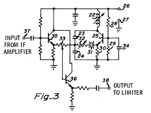
The standard FM decoder shown above did the job of FM decoding the stereo
information. The limiter is a series of differential stages that are meant
to provide so much gain that the output is in hard clipping. The input offset
of the limiter amplifier is easily handled with negative feedback using a 10Meg
resistor and a 1uF capacitor. The limiter strips all the amplitude information
off of the incoming AM signal. The square wave that is left contains only zero
crossing information.
When a clipped 455KHz signal and a 90 degree phase shifted clipped 455KHz signal get
applied to a four quadrature multiplier, the output of the will be pure 910KHz
with a DC offset of zero. But when the frequency of the 455KHz signal is Frequency
shifted above and below there the 556uH inductor and 220pF capacitor are resonant,
then the resulting phase shift produces an audio frequency output. This is a standard
FM decoder. The variable 200 Ohm Resistor defines the Q for the tuned circuit which
defines the gain of the output FM.
================CONVERT_FM_TO_PM_AT_AUDIO===============
Translating the FM output to PM requires that the audio frequency signal
coming out of the multiplier should see a capacitor to integrate it.
Some of the systems were using FM at lower audio frequencies. A shunt
resistor across the capacitor would stop the integration below the desired frequency.
During all this, the DC offset needs to be completely shorted out using an inductor.
An active inductor of around 600 henries was used. This could be done using two
transconductance amplifiers and an external capacitor.
A Simulated 600 Henry Inductor
_______________________________
| |
___ | ___|\ _ _ |
|IN1|__| _|_- | \/ \/ \_|
|___| |___|\ _ _ /// | |\_/\_/
- | \/ \/ \_ | |
___ ____| /\_/\_/ | | | _ _
|IN2|__| + |/ | | |/ \/ \_
|___| | |______| /\_/\_/ |
| | + |/ |
|____________/|\_______________|
_|_
|OFF|____
|___| _|_ C_offset =0.033uf
___
|
_|_
///
FYI See OTA_VCL.pdf
The virtual inductor is shown above. Being an inductor, it represents a
short circuit to DC offset and has high enough impedance at the audio frequencies.
Besides making it easy to build large value inductors, this architecture is a special
inductor, which can monitor the DC current which the inductor is shorting out. The
voltage across C_offset provides this value. This would come in handy for
AM stereo applications.
^ VCC
/_\
____|___________
| | | 8K
8K -> <- <-
_/\ /\ /\__ `|__|'____|'___/\ /\ /\_
| \/ \/ _'| ||`_ |`_ \/ \/ |
|__ | |___| | ______|
| | 600H| |
| | _ _ _ | |
| | / \/ \/ \ | |
-> |__| () () |___| <-
`|____| |_|'
_'| |_/\ /\ /\___| |`_
| | \/ \/ 100K| |
_|_ | | _|_
/// |_____||_______| ///
| ||0.047uF|
| ___________|
| | |
|_/|\_______ |
_| |_ _| |_
__|' `|__|' `|__
|`-> <-'| |`-> <-'|
|__| |__|
| |
_| |_
__|' `|_
|`-> <-'|
|____________|
_|_
/ _ \ 520uA
\/ \/
/\_/\
\___/
_|_
///
FYI See L_C_R_F.html and R_C_Freq.html
A partially simplified schematic of how FM gets converted to audio is
shown above. All the NPNs represent the multiplier (which is drawn with most of
it's inputs connections left out). All the PNPs are being used as a common mode
DC current self-biasing circuit. The multiplier produces two
output currents, which have both an audio and RF components.
In the case of converting FM to pure PM, these two currents need to go into
an integrator, which is being done with the 0.047uF capacitor. For systems which
used both FM and PM, the size of 100KOhm resistor relative to the 0.047uF capacitor
determine the lowest frequency at which integration is taking place (33Hz).
At much lower than audio frequencies, the 600 Henry inductor begins to short out
all DC errors. The fact that the effective DC current can be monitored
from this inductor means that it is possible to detect how much the radio is mistuned
from a station. If the radio is mistuned, the IF frequency will not
produce an average 90 degree phase shift between the two multiplier
inputs. The mistuning detection feature in the inductor provide customers with a free
Automatic Frequency Control (AFC) signal, which can be applied back to the
input tuning circuitry.
================SINGLE_SIDEBAND_NEED_90_PHASE_SHIFTERS===============
Four of the five proposed AM stereo system could therefore be covered with
one IC which used slightly different external components for each system.
The Kahn system would require additional 90 degree audio phase shift circuitry.
This is done using all pass filters. An All pass filter is the result of
adding a low pass and a high pass to a negative bandpass. Its transfer function
is given below.
all_pass_filter = (s^2 -(wo/Q)*s +wo^2)/(s^2 +(wo/Q)*s +wo^2)
( FYI see the enclosed Notes below on filters )
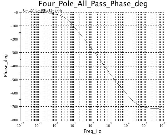
A two pole all pass produces the following phase shift versus frequency output.
Depending on the degree of precision that is required, more poles can be added.
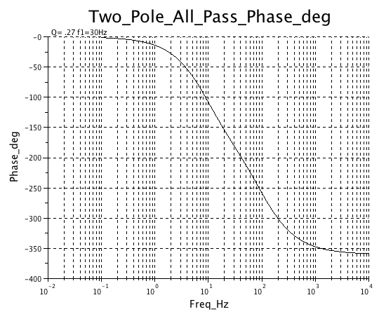
The phase shift is done by making two all pass filters, which always have a 90 degrees
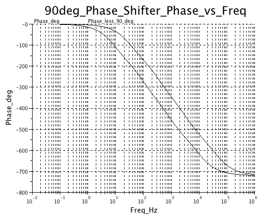
of offset phase shift between them. A four pole version is shown below.
Making two precise all pass filters which track each other
with a constant phase offset of 90 degrees is not cheap. But its
more acceptable than building two slightly mistuned
radios.
================AM_AND_90_DEGREE_SHIFTED_PM===============
The requirement for phase shift can be seen by what it takes to
produce single side bands. One needs to Amplitude Modulate by the
mono (L+R) signal and then effectively phase modulate by the stereo
(L-R) signal which has been phase shifted by 90 degrees.
================SEPARATION_DEPENDS_ON_STEREO_GAIN===============
Obviously the stereo separation is going to depend on accurately phase
shifting the audio back 90-degrees for cancelation to take place between
the (L+R) signal and the (L-R) signal. The left channel is the result of adding
stereo to mono and the right channel is subtracting stereo from mono. A measure
of goodness is how well the cancelation takes place. Channel separations around
30dB are common.
================PILOT_DETECTION==============================
National Semiconductor's universal AM Stereo decoder IC (LM1981) came out before
the FCC had decided on any system. Radio manufactures like Delco Electronics placed
particular importance on pilot signal detection. The pilots were of course different for
each system. Systems like Magnavox were non synchronous. They therefore could afford to
make the pilot be at 5Hz and phase modulate the carrier by +/- 4 radians
or +/- 229 degrees. Synchronous systems like motorola are need to restrict the
total phase shift to be under +/- 90 degrees. As a result, the motorola system used
a pilot at 25Hz at around +/-2.5 degrees.
Delco electronics had a special concern over the amount of time it took to detect the
stereo pilot signal. Apparently for FM stereo, people select stations based on whether
the stereo light comes on. This brought in some interesting information theory
constrains into the requirements. To honestly say one has seen a 5Hz signal,
one has to look at it for the full 200msec. This same constrain show up for FFT.
If one wants a 5Hz resolution FFT, one needs to take 200msec worth of sample data.
In fact, Heisenburg's uncertainty principle is just another way of expressing this
same relationship when it talks in terms of delta energy and delta time.
The problem with AM Stereo is that the broadcaster wants to modulate down to a
zero carrier if allowed. In fact, it was not obvious that some of them weren't going
below 100%. Now to start off, the broadcast equipment did not have any phase modulation
concerns until AM Stereo came along. The phase modulation of a typical AM radio could
get quite large and nonlinear when the carrier came close to being off. This presented
some challenges with detecting the motorola 25Hz pilot down at +/- 2.5 degree level. The
problem is not the detection of signals. The challenge is the rejections of interference
signals coming from the PM dirty AM radio stations which were out there.
================PILOT_DETECTION_USING_A_QUAD_OP_AMP==============================
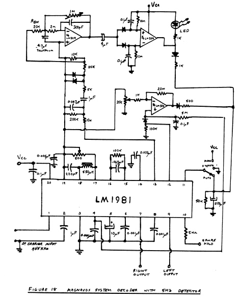
The LM1981 PC board is shown below. The pilot detection was done using a quad Op Amp.
Some additional features were added to address the adverse reception condition. A phase
magnitude detect was also installed in the LM1981 to detect when phase modulation far
exceed the expected value.
Part of the quad Op Amp in the PC board was recruited to act as a combination
lock to detect whether reception conditions were optimum, and if not, the signal
would get blended back to mono.
================EXCESSIVE_AMPLITUDE_MODULATION=============================
But still a problem remained with the broadcaster. To increase station revenue, modulation
gets pushed up as high as possible to maximize reception range. Now Motorola was also
getting into the transmitter business. It would have been interesting to see how the concept
of keeping modulation levels at a reasonable level was sold to the broadcasters.
But was there another way to solve this problem? If the broadcast could not be trusted
to control their index of modulation, could something be put in the radio to make up
the difference?
A method was found that worked extremely well. What if the index of modulation could be
adjusted at the receiver? The method that worked is shown below. The IF signal
gets injection locked to a crystal oscillator. Then this stable carrier signal
gets blended back with the input IF.
Reinserting some more carrier into the IF is not changing the audio signal.
All audio is in the sidebands. Only the carrier level is getting adjusted. In effect,
if you can't get the broadcasters to control their modulation, why not then fix things
at the receiver? Reception wise, this appeared to make a huge night and day difference.
If AM stereo had taken a different direction, this carrier re-insertion technique
would have been incorporated into the decoder IC using a phase lock loop.
================MOTOROLA'S_AM_STEREO_EFFORT=============================
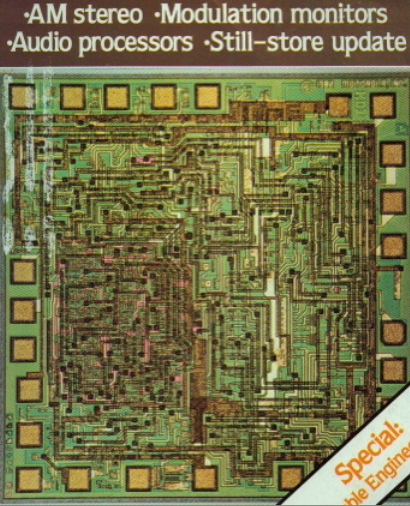
National Semiconductor's effort stopped when the engineers from Motorola
convinced Management at Delco Electronics that the Motorola system was
better than the Magnavox system. At the time, National's AM Stereo IC was
representing the Magnavox system, because by this time the company of Magnavox
had long ceased to exist. Only the LM1981 could supply an alternative data point
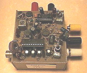
for the comparison. Motorola was also in the IC business, as is shown above
by the photograph of their decoder IC. And they wanted no IC decoder competition. They
wanted the whole package. The IC decoders, the transmitters, everything.
Apparently the FCC finally declared motorola the winner. They certainly hung
in there.
======================CUT_AND_PASTE_CODE=============================
SciLab_Templates Cut and paste the code below into a SciLab command window to run
and plot the curves. Note 3D_FFT plot can be rotated using the mouse.
AM_30% =================SciLab_Template=========================
ns =10000; // set sample rate @ 10K samples/sec
x = linspace(0,1,ns ); // make 1000 x points from 0-> 1 secs
[nc,nr]=size(x); // find size of array
for i=1:nr, y(i)=cos(2*%pi*50*x(i)) + cos(2*%pi*50*x(i))*0.3*cos(2*%pi*5*x(i)); end;
yfft = fft(y); // fft retain only first N/2 points
f = nr*(0:(nr/2))/nr; // create frequency vector
nf=size(f,'*') // check size of freq vector
fr= real(yfft(1:nf)/nr); // find real of fft
fi= imag(yfft(1:nf)/nr); // find imag of fft
for i=1:100, b(i) =i ; end; // make a bin array to plot first 100 bins
param3d( b/100, fi(b),fr(b),-35,57,"jw_Hz/100@imag@real",[1,4],[-1,1,-1,1,-1,1]);
param3d(-b/100,-fi(b),fr(b),-35,57,"jw_Hz/100@imag@real",[1,4],[-1,1,-1,1,-1,1]);
for i=1:100, zer(i) =0 ; end; //make a zero array
param3d(zer(b),b/100,zer(b),-35,57,"jw_Hz/100@imag@real",[1,4],[-1,1,-1,1,-1,1]);
e=gce(); e.foreground=color('red'); //the handle on the 3D polyline
param3d(zer(b),-b/100,zer(b),-35,57,"jw_Hz/100@imag@real",[1,4],[-1,1,-1,1,-1,1]);
e=gce(); e.foreground=color('red'); //the handle on the 3D polyline
param3d(zer(b),zer(b),-b/100,-35,57,"jw_Hz/100@imag@real",[1,4],[-1,1,-1,1,-1,1]);
e=gce(); e.foreground=color('red'); //the handle on the 3D polyline
param3d(zer(b),zer(b),b/100,-35,57,"jw_Hz/100@imag@real",[1,4],[-1,1,-1,1,-1,1]);
e=gce(); e.foreground=color('red'); //the handle on the 3D polyline
xtitle("y(i)=cos(2*%pi*50*x(i)) + cos(2*%pi*50*x(i))*0.3*cos(2*%pi*5*x(i))")
Quad_PM_30% =================SciLab_Template=========================
ns =10000; // set sample rate @ 10K samples/sec
x = linspace(0,1,ns ); // make 1000 x points from 0-> 1 secs
[nc,nr]=size(x); // find size of array
for i=1:nr, y(i)=cos(2*%pi*50*x(i)) + sin(2*%pi*50*x(i))*0.3*cos(2*%pi*5*x(i)); end;
yfft = fft(y); // fft retain only first N/2 points
f = nr*(0:(nr/2))/nr; // create frequency vector
nf=size(f,'*') // check size of freq vector
fr= real(yfft(1:nf)/nr); // find real of fft
fi= imag(yfft(1:nf)/nr); // find imag of fft
for i=1:100, b(i) =i ; end; // make a bin array to plot first 100 bins
param3d( b/100, fi(b),fr(b),-35,57,"jw_Hz/100@imag@real",[1,4],[-1,1,-1,1,-1,1]);
param3d(-b/100,-fi(b),fr(b),-35,57,"jw_Hz/100@imag@real",[1,4],[-1,1,-1,1,-1,1]);
for i=1:100, zer(i) =0 ; end; //make a zero array
param3d(zer(b),b/100,zer(b),-35,57,"jw_Hz/100@imag@real",[1,4],[-1,1,-1,1,-1,1]);
e=gce(); e.foreground=color('red'); //the handle on the 3D polyline
param3d(zer(b),-b/100,zer(b),-35,57,"jw_Hz/100@imag@real",[1,4],[-1,1,-1,1,-1,1]);
e=gce(); e.foreground=color('red'); //the handle on the 3D polyline
param3d(zer(b),zer(b),-b/100,-35,57,"jw_Hz/100@imag@real",[1,4],[-1,1,-1,1,-1,1]);
e=gce(); e.foreground=color('red'); //the handle on the 3D polyline
param3d(zer(b),zer(b),b/100,-35,57,"jw_Hz/100@imag@real",[1,4],[-1,1,-1,1,-1,1]);
e=gce(); e.foreground=color('red'); //the handle on the 3D polyline
xtitle("y(i)=cos(2*%pi*50*x(i)) + sin(2*%pi*50*x(i))*0.3*cos(2*%pi*5*x(i))")
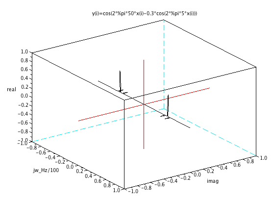
PM_30% =================SciLab_Template=========================
ns =10000; // set sample rate @ 10K samples/sec
x = linspace(0,1,ns ); // make 1000 x points from 0-> 1 secs
[nc,nr]=size(x); // find size of array
for i=1:nr, y(i)=cos(2*%pi*50*x(i)-0.3*cos(2*%pi*5*x(i))); end;
yfft = fft(y); // fft retain only first N/2 points
f = nr*(0:(nr/2))/nr; // create frequency vector
nf=size(f,'*') // check size of freq vector
fr= real(yfft(1:nf)/nr); // find real of fft
fi= imag(yfft(1:nf)/nr); // find imag of fft
for i=1:100, b(i) =i ; end; // make a bin array to plot first 100 bins
param3d( b/100, fi(b),fr(b),-35,57,"jw_Hz/100@imag@real",[1,4],[-1,1,-1,1,-1,1]);
param3d(-b/100,-fi(b),fr(b),-35,57,"jw_Hz/100@imag@real",[1,4],[-1,1,-1,1,-1,1]);
for i=1:100, zer(i) =0 ; end; //make a zero array
param3d(zer(b),b/100,zer(b),-35,57,"jw_Hz/100@imag@real",[1,4],[-1,1,-1,1,-1,1]);
e=gce(); e.foreground=color('red'); //the handle on the 3D polyline
param3d(zer(b),-b/100,zer(b),-35,57,"jw_Hz/100@imag@real",[1,4],[-1,1,-1,1,-1,1]);
e=gce(); e.foreground=color('red'); //the handle on the 3D polyline
param3d(zer(b),zer(b),-b/100,-35,57,"jw_Hz/100@imag@real",[1,4],[-1,1,-1,1,-1,1]);
e=gce(); e.foreground=color('red'); //the handle on the 3D polyline
param3d(zer(b),zer(b),b/100,-35,57,"jw_Hz/100@imag@real",[1,4],[-1,1,-1,1,-1,1]);
e=gce(); e.foreground=color('red'); //the handle on the 3D polyline
xtitle("y(i)=cos(2*%pi*50*x(i)-0.3*cos(2*%pi*5*x(i)))")
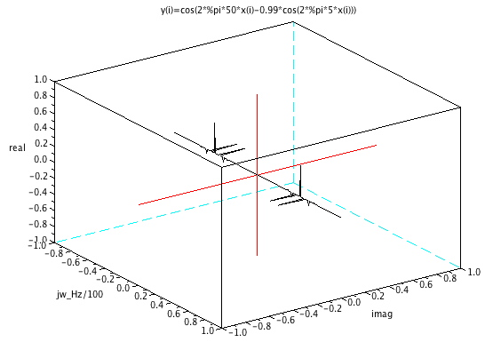
PM_99% =================SciLab_Template=========================
ns =10000; // set sample rate @ 10K samples/sec
x = linspace(0,1,ns ); // make 1000 x points from 0-> 1 secs
[nc,nr]=size(x); // find size of array
for i=1:nr, y(i)=cos(2*%pi*50*x(i)-0.99*cos(2*%pi*5*x(i))); end;
yfft = fft(y); // fft retain only first N/2 points
f = nr*(0:(nr/2))/nr; // create frequency vector
nf=size(f,'*') // check size of freq vector
fr= real(yfft(1:nf)/nr); // find real of fft
fi= imag(yfft(1:nf)/nr); // find imag of fft
for i=1:100, b(i) =i ; end; // make a bin array to plot first 100 bins
param3d( b/100, fi(b),fr(b),-35,57,"jw_Hz/100@imag@real",[1,4],[-1,1,-1,1,-1,1]);
param3d(-b/100,-fi(b),fr(b),-35,57,"jw_Hz/100@imag@real",[1,4],[-1,1,-1,1,-1,1]);
for i=1:100, zer(i) =0 ; end; //make a zero array
param3d(zer(b),b/100,zer(b),-35,57,"jw_Hz/100@imag@real",[1,4],[-1,1,-1,1,-1,1]);
e=gce(); e.foreground=color('red'); //the handle on the 3D polyline
param3d(zer(b),-b/100,zer(b),-35,57,"jw_Hz/100@imag@real",[1,4],[-1,1,-1,1,-1,1]);
e=gce(); e.foreground=color('red'); //the handle on the 3D polyline
param3d(zer(b),zer(b),-b/100,-35,57,"jw_Hz/100@imag@real",[1,4],[-1,1,-1,1,-1,1]);
e=gce(); e.foreground=color('red'); //the handle on the 3D polyline
param3d(zer(b),zer(b),b/100,-35,57,"jw_Hz/100@imag@real",[1,4],[-1,1,-1,1,-1,1]);
e=gce(); e.foreground=color('red'); //the handle on the 3D polyline
xtitle("y(i)=cos(2*%pi*50*x(i)-0.99*cos(2*%pi*5*x(i)))")
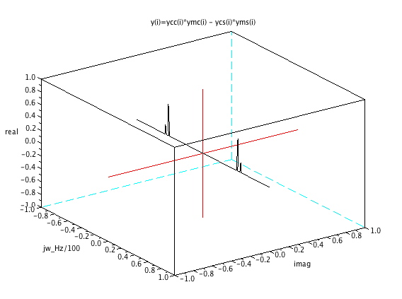
Single_Sideband_30% =================SciLab_Template=========================
ns =10000; // set sample rate @ 10K samples/sec
x = linspace(0,1,ns ); // make 1000 x points from 0-> 1 secs
[nc,nr]=size(x); // find size of array
ycc=cos(2*%pi*50*x);
ycs=sin(2*%pi*50*x);
ymc=0.3*cos(2*%pi*5*x) +1 ;
yms=0.3*sin(2*%pi*5*x);
for i=1:nr, y(i)=ycc(i)*ymc(i) - ycs(i)*yms(i) ; end;
yfft = fft(y); // fft retain only first N/2 points
f = nr*(0:(nr/2))/nr; // create frequency vector
nf=size(f,'*') // check size of freq vector
fr= real(yfft(1:nf)/nr); // find real of fft
fi= imag(yfft(1:nf)/nr); // find imag of fft
for i=1:100, b(i) =i ; end; // make a bin array to plot first 100 bins
param3d( b/100, fi(b),fr(b),-35,57,"jw_Hz/100@imag@real",[1,4],[-1,1,-1,1,-1,1]);
param3d(-b/100,-fi(b),fr(b),-35,57,"jw_Hz/100@imag@real",[1,4],[-1,1,-1,1,-1,1]);
for i=1:100, zer(i) =0 ; end; //make a zero array
param3d(zer(b),b/100,zer(b),-35,57,"jw_Hz/100@imag@real",[1,4],[-1,1,-1,1,-1,1]);
e=gce(); e.foreground=color('red'); //the handle on the 3D polyline
param3d(zer(b),-b/100,zer(b),-35,57,"jw_Hz/100@imag@real",[1,4],[-1,1,-1,1,-1,1]);
e=gce(); e.foreground=color('red'); //the handle on the 3D polyline
param3d(zer(b),zer(b),-b/100,-35,57,"jw_Hz/100@imag@real",[1,4],[-1,1,-1,1,-1,1]);
e=gce(); e.foreground=color('red'); //the handle on the 3D polyline
param3d(zer(b),zer(b),b/100,-35,57,"jw_Hz/100@imag@real",[1,4],[-1,1,-1,1,-1,1]);
e=gce(); e.foreground=color('red'); //the handle on the 3D polyline
xtitle("y(i)=ycc(i)*ymc(i) - ycs(i)*yms(i) ")
======================FILTERS_STATE_VARIABLE===============================
Filters high_pass = (s^2 )/(s^2 +(wo/Q)*s +wo^2)
band_pass = ( +(wo/Q)*s )/(s^2 +(wo/Q)*s +wo^2)
low_pass = ( wo^2)/(s^2 +(wo/Q)*s +wo^2)
all_pass = (s^2 -(wo/Q)*s +wo^2)/(s^2 +(wo/Q)*s +wo^2)
band_rej = (s^2 +wo^2)/(s^2 +(wo/Q)*s +wo^2)
__
_____|b2|________________
| |__| __ |
| ____|b1|_______ |
| | |__| | |
___ .. | |. V_V
U(z) _ / _ \ y(t)| ___ |y(t) ___ y(t) / _ \
_\|k|_\/ \ \_____|_|1/z|_|____|1/z|___\/ \ \_\
/|_| /\ /_ / |___| | |___|| /\ /_ / /
\___/ | | \___/ Y(z)
^ ^ _____ | |
| |___| -a2 |______| |
| |_____| ___ |
|_____________|-a1|_________|
|___|
Y(z)/U(z) =K (1+ z*b1 + z*b2) /( z^2 +a2*z +a1)
__
_____|b2|________________
| |__| __ |
| ____|b1|_______ |
| | |__| | |
___ .. | |. V_V
U(S) _ / _ \ y(t)| ___ |y(t) ___ y(t) / _ \
_\|k|_\/ \ \_____|_|1/s|_|____|1/s|___\/ \ \_\
/|_| /\ /_ / |___| | |___|| /\ /_ / /
\___/ | | \___/ Y(S)
^ ^ _____ | |
| |___| -a2 |______| |
| |_____| ___ |
|_____________|-a1|_________|
|___|
Y(S)/U(S) =K (1+ s*b1 + s*b2) /( s^2 +a2*s +a1)
____
___||_ ____||_|Y(S)|
| || | | ||||____|
| |\ C| | |\ C |
____ Rk R | |-\ | R | |-\ |
|U(S)|_/\ /\__/\ /\_|_| \_|_/\ /\_|_| \_|
|____| \/ | \/ | /| \/ | /|
| ____|+/ | ____|+/ |
| _|_ |/ | _|_ |/ |
| /// | /// |
Rsum | | |
| Ra2 | |
_/\ /\_|_______/\ /\| |
_|_ \/ | \/ Ra1 |
/// |___________________/\ /\___|
K =Rsum/(Rsum+Rk) \/
a2 =Rsum/(Rsum+Ra2)
a1 =Rsum/(Rsum+Ra1)
s=1 when Xc = R
___ .. .
U(S) ___ / _ \ y(t) _____ y(t) _____ y(t)
_\| k |_\/ \ \_____| 1/s |_____| 1/s |_______\ Y(S)
/|___| /\ /_ / |_____| | |_____| | /
\___/ | |
^ ^ _____ | |
| |___| -a2 |_______| |
| |_____| _____ |
|_____________| -a1 |__________|
|_____|
Y(S)/U(S) =K/( s^2 +a2*s +a1)
======================PHASE_Shifters===============================
SciLab_Templates Cut and paste into a SciLab command window to run
plots of gain_dB and Phase_deg
All_Pass =================SciLab_Template=========================
w01=2*%pi*30
Q=.27
freqmax=10000
freqstep=.005
freqmin=.1
Phmax=20
Phmin=-180
s=poly(0,'s') // define s as a poly symbol
h1=syslin('c',(s^2-s*w01/Q +w01^2)/(s^2+s*w01/Q+w01^2))
[frq1,rf1]=repfreq(h1,freqmin,freqmax,freqstep); // create complex frq response
[db1,phi1]=dbphi(rf1); // extact db phase vectors
xstring(0.01,1.1,["Q= .27 f1=30Hz"])
xgrid();
plot2d(frq1,phi1,logflag="ln")
xtitle("Two_Pole_All_Pass_Phase_deg","Freq_Hz","Phase_deg");
a=get("current_axes");
t=a.title;
t.font_size=5;
t=a.x_label;
t.font_size=3;
t=a.y_label;
t.font_size=3;
Four_Pole_All_Pass =================SciLab_Template=========================
w01=2*%pi*30
w02=2*%pi*3000
Q=.27
freqmax=1000000
freqstep=.005
freqmin=.1
Phmax=20
Phmin=-180
s=poly(0,'s')
h1=syslin('c',(s^2-s*w01/Q +w01^2)*(s^2-s*w02/Q+w02^2)/((s^2+s*w01/Q+w01^2)*(s^2+s*w02/Q+w02^2)))
[frq1,rf1]=repfreq(h1,freqmin,freqmax,freqstep);
[db1,phi1]=dbphi(rf1);
xstring(0.01,1.1,["Q= .27 f1=30Hz f2=3kHz"])
xgrid();
plot2d(frq1,phi1,logflag="ln")
xtitle("Four_Pole_All_Pass_Phase_deg","Freq_Hz","Phase_deg");
a=get("current_axes");
t=a.title;
t.font_size=5;
t=a.x_label;
t.font_size=3;
t=a.y_label;
t.font_size=3;
Audio_Phase_Shifter =================SciLab_Template=========================
w01=2*%pi*30
w02=2*%pi*3000
w03=2*%pi*120
w04=2*%pi*12000
Q=.27
freqmax=1000000
freqstep=.005
freqmin=.1
Phmax=20
Phmin=-180
s=poly(0,'s')
h1=syslin('c',(s^2-s*w01/Q +w01^2)*(s^2-s*w02/Q+w02^2)/((s^2+s*w01/Q+w01^2)*(s^2+s*w02/Q+w02^2)))
h2=syslin('c',(s^2-s*w03/Q +w03^2)*(s^2-s*w04/Q+w04^2)/((s^2+s*w03/Q+w03^2)*(s^2+s*w04/Q+w04^2)))
[frq1,rf1]=repfreq(h1,freqmin,freqmax,freqstep);
[db1,phi1]=dbphi(rf1);
[frq2,rf2]=repfreq(h2,freqmin,freqmax,freqstep);
[db2,phi2]=dbphi(rf2);
xstring(0.01,1.1,["Phase_deg "])
xstring(.8,1.1,["Phase_less_90_deg "])
xgrid();
plot2d(frq1,phi1,logflag="ln")
plot2d(frq2,phi2,logflag="ln")
xtitle("90deg_Phase_Shifter_Phase_vs_Freq","Freq_Hz","Phase_deg");
a=get("current_axes");
t=a.title;
t.font_size=5;
t=a.x_label;
t.font_size=3;
t=a.y_label;
t.font_size=3;