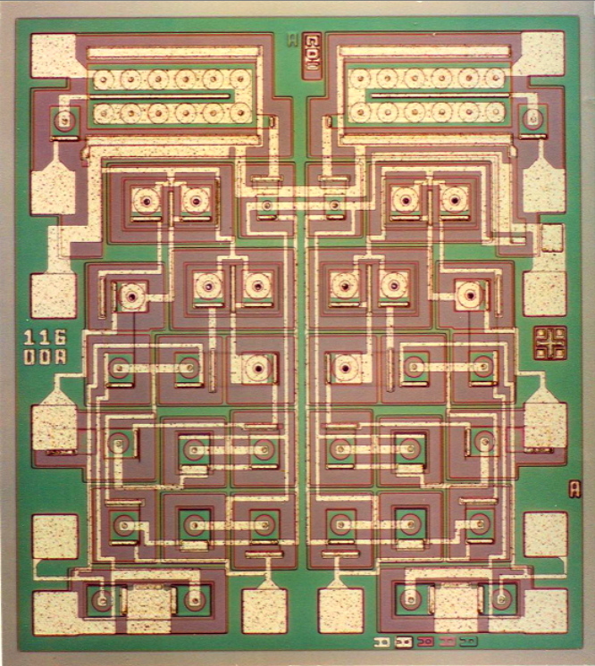
The Photo above is of the LM13600/13700 STEREO Transconductance Amplifier.{DATASHEET.PDF}
The LM13600 has designed by Bill Gross and myself in less than 5 minutes.
At the time the Consumer Linear IC design group was training a new mask designer.
We needed something with a few transistors for her to learn how to arrange them in a
optimum circuit arrangement while using minimum silicon area.
At the time, electronic Organs were being done using analog circuitry. I had just
made a trip to one such company and of course they gave me a wish list of what
kind of circuits they would like to see. The RCA 3080 has just come out and it almost
gave the Analog Organ folks everything they wanted. They needed something for analog
variable gain. The application was to shape the attack and decay of various waveforms.
But the 3080 was a true Operational Transconductance Amplifier in that it had a
voltage input and a current source output. For most applications, an external buffer
was needed.
At the time we were considering second sourcing the 3080 anyway.
Also at this very same time, the 16pin plastic dip package had just been developed.
So the development spec for the LM13600 was that it needed a schematic to train someone
in IC layout. It needed to have 16 pins. And we were going to layout the 3080 anyway.
The schematic part was easy. Just used the 3080 exactly. There were 16 pins, so we could
just mirror the layout to do a stereo. That left 3 extra pins per channel. The simplest
buffer was a darlington which needed two pins per channel. There were complaints about
high levels in input signal generated too much distortion in the 3080. That could be
addressed by connecting the left over pin to predistortion diodes.
After layout, Tim Isbell the design manager decided to just go ahead and make it a product.
First silicon work even with very unusual beta. This last fact explains why both
the LM13600 and LM13700 came out together. Control of beta was not tight at the time
and all transistors needed to be biased up with currents well above the leakage
current levels in the process. One way to do that was to use area scaling to force
the beta of the output transistor in the darlington to 50. That what was used to
the LM13700.The other method involve feeding some of the control current back to
the darlington. At the time, this enabled the LM13600 to have usable dynamic
range well above 96dB.
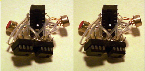
An actual breadboard of the LM13600 has made after it was decided to build the IC.
As shown above, it was just two LM3080s and NPN kit parts wired up to have the
same pinout. (How to view stereo graphic images as above is being discussed here.)
This breadboard served the purpose of having a characteriztion test box ready and
waiting for the first silicon.
The development of the datasheet borrowed heavily from the quad Opamp datasheets.
Now that you were giving the customer something they never had before, what new things
could now be done? All the application circuits were developed and debugged in
the lab. I was thinking about publishing an article in Popular Electronics. But I did
not need to. About ten years later Radio Electronics copied my data sheets into two
of their articles almost verbatim here and also here and also here.
At the time of doing the datasheet, management was beginning to think that the number
of application examples were getting out of hand. Today Operational Transconductance
Amplifiers can be defined in Spice using only a single line. Some Spice Simulations
using this feature have therefore been added to this website.
In addition to the datasheet, some additional application examples
can be found here. And perhaps a more accurate spice model needs
to have better transistor models.
Other Integrated circuit development stories and design resources
can be found here.
Don Sauer... DSauerSanJose@Aol.com