Look Inside GDSII


In an attempt to address that helpless feeling that comes when a GDSII file will sometimes not work,
a simple CPP program has been written to be able to look inside and experiment with a GDSII binary file.

M1TEST.jpg

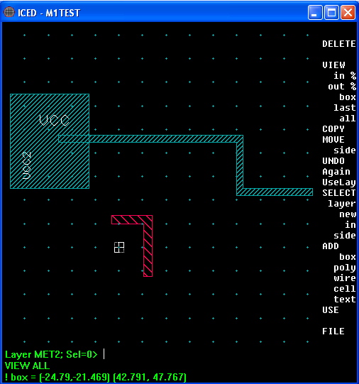
An IC layout essentially involves the placement of objects often referred to as geometries.
Geometries are things like boxes (polygons), paths (wires), text (strings), etc.
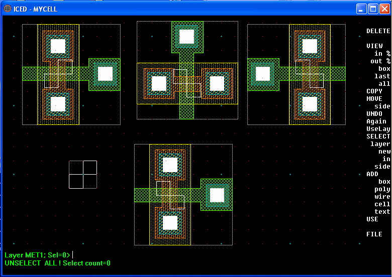
Transistors are made out of a collection of geometries  grouped together in a file which is called a cell.
A circuit mainly involves just placing a bunch of transistor cells together and wiring  all their nodes up using metal layer wires.
Text can (should) be added to make the layout process much easier.
The layout below adds an example of all those geometries.
Both GDSII and layout files are normally stored in binary format.
ICEDIT also has a way to print out a layout in text format.

==============================ICEDIT.txt========================================
! Selected components in M1TEST:
ADD  BOX             LAYER=MET1  ID=1                           AT (-23.1, 12.5) (-6.4, 32.5)
ADD  CELL "AT_ZERO"              ID=5                           AT (  0.0,  0.0)
ADD  TEXT="VCC2"     LAYER=MET1  ID=4  SIZE=2.000  JUST=LB  R1  AT (-18.7, 14.4)
ADD 
TEXT="VCC"      LAYER=MET1  ID=3  SIZE=3.000  JUST=LB      AT (-17.0, 25.4)
ADD  WIRE            LAYER=MET2  ID=6  TYPE=2  WIDTH=1.800      AT ( -0.7,  5.9) (6.2, 5.9) (6.2,-5.3)
ADD 
WIRE            LAYER=MET1  ID=2  TYPE=2  WIDTH=1.400      AT (-12.1, 23.0) &
                                                                   ( 25.6, 23.0) (25.6, 11.7) (40.4, 11.7)
! layer:   perimeter         area   wire length
!- MET1      206.600       425.28       130.400
!- MET2       43.400        35.82        19.900


When a GDSII file is translated to text format (shown below) is in a similar style.
Each piece of data in a
GDSII is stored in own  self contained block of code.
The first two bytes read in tell how big the block is.
The second two bytes tell what the block does.
And the remaining bytes are  read into a simple byte array which can either  be a number(s) or text.

==============================GDSII.txt========================================
 HEADER         Release # 3 
 BGNLIB         LIBNAME = M1TEST.DB   FONTS = GDSII:CALMAFONT.TX 
 GENERATIONS 3  UNITS   = 0.001  1e-09 
 BGNSTR         STRNAME =
M1TEST 
 BOUNDARY       LAYER   = 8   DATATYPE = 0 
 XY =           -23100 32500 -23100 12500 -6400 12500 -6400 32500 -23100 32500
 ENDEL 
 PATH           LAYER   = 8   DATATYPE = 0 
 PATHTYPE 2     WIDTH     1400 
 XY =           -12100 23000 25600 23000 25600 11700 40400 11700
 ENDEL 
 
TEXT           LAYER   = 8   TEXTTYPE 0   PRESENTATION 8   STRANS none  MAG 3
 XY =           -17000 25400
 STRING         VCC 
 ENDEL 
 
TEXT           LAYER   = 8   TEXTTYPE 0   PRESENTATION 8   STRANS none  MAG 2  ANGLE 90 
 XY =           -18700 14400
 STRING         VCC2 
 ENDEL 
 SREF           SNAME     AT_ZERO   STRANS none  XY =           0 0
 ENDEL 
 
PATH           LAYER   = 10   DATATYPE = 0 
 PATHTYPE 2     WIDTH     1800 
 XY =           -700 5900 6200 5900 6200 -5300
 ENDEL 
 ENDSTR 
 
BGNSTR         STRNAME = AT_ZERO 
 
BOUNDARY       LAYER   = 50   DATATYPE = 1 
 XY =           -1000 0 -1000 -1000 0 -1000 0 0 -1000 0
 ENDEL 
 
BOUNDARY       LAYER   = 50   DATATYPE = 1 
 XY =           0 1000 0 0 1000 0 1000 1000 0 1000
 ENDEL 
 
ENDSTR 
 ENDLIB 

The listing above is from a printout from a simple GDSII file reader.
This programs just reads each block one at a time and prints out the Block Name ID and the value(s) contained within.
Hopefully it should be possible to read and printout a troublesome GDSII stream file until it gets into trouble.
And then go in and maybe adjust some code to look at  troublesome areas .

There are some name changes between the ICEDIT format and GDSII.
Boxes (polygons) are indicated by the BOUNDARY ID.
Wires (path) are PATHS which have a width.
A Cell seems to the geometries contained  inside the BGNSTR  and ENDSTR IDs.
The placement of a cell appears to use the SREF ID.
All Cells which are referenced are completely contained in the GDSII file.

==============================BiCMOSLAYERS.cmd========================================

VIEW OFF
$ MENU "M1";                       KEEP_LIBRARY_CELLS=ASK;   DISPLAY CELL_DEPTH=100;
PATTERN     "SAMPLE";              FILL MIXED ON
AUTOPAN ON  PIXELS=100             SECONDS=0.5;              ARROW MODE=EDIT
DISPLAY     CELL_LABELS=ON         OUTLINE_DEPTH=1           EDIT_STACK=OFF  CURSOR 1           SNAP=ON
SPACER OFF  SPACE=0.0              TRACK_LAYERS=OFF          STYLE=1
VIEW        LIMIT ON               SCALE=0.100               DEPTH=1         DOTS=0 UNITS=0.0   SHOW_LAYERS 1:*
ARRAY       DRAW_MODE=SIDES        CELL_LIMIT=1024
TEXT        LOWER_CASE=DISABLED    MULTI_LINE_TEXT=DISABLED  ORIENTATIONS=2  DISPLAY_ORIGINS=OFF
USE         TEXT_JUSTIFICATION=LB  WIRE_TYPE=2               ARC_TYPE=2      N_SIDES=16
RESOLUTION  STEP=0.100             MODE=SOFT
SNAP        ANGLE=45               STEP=(0.100,0.100)        OFFSET=(0.000,0.000)
NEAR        UNITS=0.05             DOTS=4

GRID 1  ON   COLOR=RED     DOTS     STEP=1.0
GRID 2  ON   COLOR=CYAN    CROSSES  STEP=5
GRID 3  OFF  COLOR=WHITE   LINES    STEP=50000

LAYER 1   NAME=NWEL     WIDTH=1.300  SPACE=4.200  DIM_BLUE  PAT=13   PEN=16  NO_CIF    STREAM=1,0
LAYER 2   NAME=COMP     WIDTH=1.000  SPACE=1.700  ORANGE    PAT=29   PEN=*   NO_CIF    STREAM=2,0
LAYER 3   NAME=PFIELD   WIDTH=4.300  SPACE=2.200  GRAY      PAT=0    PEN=*   NO_CIF    STREAM=3,0
LAYER 4   NAME=POLY     WIDTH=1.000  SPACE=1.000  GREEN     PAT=20   PEN=*   NO_CIF    STREAM=4,0
LAYER 5   NAME=NPLUS    WIDTH=1.300  SPACE=0.000  YELLOW    PAT=15   PEN=*   NO_CIF    STREAM=5,0
LAYER 6   NAME=PPLUS    WIDTH=1.300  SPACE=0.000  ORANGE    PAT=15   PEN=*   NO_CIF    STREAM=6,0
LAYER 7   NAME=CONT     WIDTH=1.000  SPACE=1.000  WHITE     PAT=1    PEN=*   NO_CIF    STREAM=7,0
LAYER 8   NAME=MET1     WIDTH=1.400  SPACE=1.200  CYAN      PAT=3    PEN=*   NO_CIF    STREAM=8,0
LAYER 9   NAME=VIA      WIDTH=1.000  SPACE=1.000  YELLOW    PAT=1    PEN=*   NO_CIF    STREAM=9,0
LAYER 10  NAME=MET2     WIDTH=1.800  SPACE=1.400  RED       PAT=13   PEN=*   NO_CIF    STREAM=10,0
LAYER 40  NAME=NBURIED  WIDTH=1.000  SPACE=0.000  YELLOW    PAT=34   PEN=*   NO_CIF    STREAM=21,0


There are some detail set by Process_Layer_File which will define things like resolution and calma number for each layer.
A edited version of this file is shown above.

==============================Cell_Placement_Details========================================

Things like cell rotation and hierarchy need to be included in a GDSII file as well.
The text printout for this layout above shows only cell placement and rotation information.


MYCELL.jpg


==============================ICEDIT.txt========================================
ADD  CELL "NMOS"     ID=143      AT (-1.8, 7.3)
ADD 
CELL "AT_ZERO"  ID=141      AT ( 0.0, 0.0)
ADD 
CELL "NMOS"     ID=146  MY  AT ( 6.3,-1.5)
ADD 
CELL "NMOS"     ID=145  MX  AT (16.4, 7.3)
ADD 
CELL "NMOS"     ID=144  R1  AT ( 7.5, 6.6)

This is not a problem for layout since the all the cell are usually contained in one directory.
But the GDSII file needs to contain all cell geometries including  cells that are placed inside other cells.
 
==============================GDSII.txt========================================
 HEADER         Release # 3 
 BGNLIB         LIBNAME = MYCELL.DB   FONTS = GDSII:CALMAFONT.TX 
 GENERATIONS 3  UNITS   = 0.001  1e-09 
 BGNSTR         STRNAME = MYCELL 
 SREF           SNAME     AT_ZERO STRANS none                XY = 0 0
 ENDEL 
 
SREF           SNAME     NMOS    STRANS none                XY = -1800 7300
 ENDEL 
 
SREF           SNAME     NMOS    STRANS none     ANGLE 90   XY = 7500 6600
 ENDEL 
 
SREF           SNAME     NMOS    STRANS reflect  ANGLE 180  XY = 16400 7300
 ENDEL 
 
SREF           SNAME     NMOS    STRANS reflect             XY = 6300 -1500
 ENDEL 
 ENDSTR 
 
BGNSTR         STRNAME = AT_ZERO 
 BOUNDARY       LAYER   = 50   DATATYPE = 1 
 XY =           -1000 0 -1000 -1000 0 -1000 0 0 -1000 0
 ENDEL 
 
BOUNDARY       LAYER   = 50   DATATYPE = 1 
 XY =           0 1000 0 0 1000 0 1000 1000 0 1000
 ENDEL 
 
ENDSTR 
 
BGNSTR         STRNAME = NMOS 
 
BOUNDARY       LAYER   = 5   DATATYPE = 0 
 XY =           -1500 3600 -1500 -3700 1500 -3700 1500 3600 -1500 3600
 ENDEL 
 
BOUNDARY       LAYER   = 7   DATATYPE = 0 
 XY =           2900 500 2900 -500 3900 -500 3900 500 2900 500
 ENDEL 
 
BOUNDARY       LAYER   = 8   DATATYPE = 0 
 XY =           2600 800 2600 -800 4200 -800 4200 800 2600 800
 ENDEL 
 BOUNDARY       LAYER   = 4   DATATYPE = 0 
 XY =           2200 1100 4500 1100 4500 -1200 2200 -1200 2200 -500 -2600 -500 -2600 500 2200 500 2200 1100
 ENDEL 
 
BOUNDARY       LAYER   = 7   DATATYPE = 0 
 XY =           -500 -1700 -500 -2700 500 -2700 500 -1700 -500 -1700
 ENDEL 
 
BOUNDARY       LAYER   = 8   DATATYPE = 0 
 XY =           -800 -1400 -800 -3000 800 -3000 800 -1400 -800 -1400
 ENDEL 
 
BOUNDARY       LAYER   = 7   DATATYPE = 0 
 XY =           -500 2500 -500 1500 500 1500 500 2500 -500 2500
 ENDEL 
 
BOUNDARY       LAYER   = 8   DATATYPE = 0 
 XY =           -800 2800 -800 1200 800 1200 800 2800 -800 2800
 ENDEL 
 
BOUNDARY       LAYER   = 2   DATATYPE = 0 
 XY =           -1100 -1100 -600 -1100 -600 900 -1100 900 -1100 3100 1100 3100 1100 900 500 900 500
                -1100 1100 -1100 1100 -3300 -1100 -3300 -1100 -1100
 ENDEL 
 
SREF           SNAME  AT_ZERO   STRANS none  XY =           0 0
 ENDEL 
 
ENDSTR 
 ENDLIB 


The GFDSII format of storing all information is shown above.
Apparantly a mirror in the X direction is being done with a reflection and a 180 degree rotation.

The simple GDSII_read_Program is given here for reference sake only.
This program is written more in a style to make some hard to see critical details stand out.
It was written on a MacBook and is intended more for personal debugging purposes.
There are several GDSII translation programs online which do the same thing.
The latest mac version is GdsDump-OSX.
So far, the GdsDump-OSX program has yet to crash on a GDSII file. 
For information sake, the following are listings of the various types of blocks.


==============================GDSII_REF========================================
Nr Code Mnemonic      Data Type description
0  0002 HEADER        Two-Byte Signed Integer version number
1  0102 BGNLIB        Two-Byte Signed Integer begin of library, last modification date and time
2  0206 LIBNAME       Two-Byte Signed Integer name of library
3  0305 UNITS         Eight-Byte Real user and database units
4  0400 ENDLIB        No Data end of library
5  0502 BGNSTR        Two-Byte Signed Integer begin of structure + creation and modification time
6  0606 STRNAME       ASCII string name of structure
7  0700 ENDSTR        No Data end of structure
8  0800 BOUNDARY      No Data begin of boundary element
9  0900 PATH          No Data begin of path element
10 0A00 SREF          No Data begin of structure reference element
11 0B00 AREF          No Data begin of array reference element
12 0C00 TEXT          No Data begin of text element
13 0D02 LAYER         Two-Byte Signed Integer layer number of element
14 0E02 DATATYPE      Two-Byte Signed Integer Datatype number of element
15 0F03 WIDTH         Four-Byte Signed Integer width of element in db units
16 1003 XY            Four-Byte Signed Integer list of xy coordinates in db units
17 1100 ENDEL         No Data end of element
18 1206 SNAME         ASCII string name of structure reference
19 1302 COLROW        Two-Byte Signed Integer number of colomns and rows in array reference
21 1500 NODE          No Data begin of node element
22 1602 TEXTTYPE      Two-Byte Signed Integer texttype number
23 1701 PRESENTATION  Bit Array text presentation, font
25 1906 STRING        ASCII string character string for text element
26 1A01 STRANS        Bit Array array reference, structure reference and text transform flags
27 1B05 MAG           Eight Byte Real magnification factor for text and references
28 1C05 ANGLE         Eight Byte Real rotation angle for text and references
31 1F06 REFLIBS       ASCII string name of referenced libraries
32 2006 FONTS         ASCII string name of text fonts definition files
33 2102 PATHTYPE      Two-Byte Signed Integer type of PATH element end ( rounded, square)
34 2202 GENERATIONS   Two-Byte Signed Integer number of deleted structure ?????
35 2306 ATTRTABLE     ASCII string attribute table, used in combination with element properties
38 2601 ELFLAGS       Two-Byte Signed Integer template data
42 2A02 NODETYPE      Two-Byte Signed Integer node type number for NODE element
43 2B02 PROPATTR      Two-Byte Signed Integer attribute number
44 2C06 PROPVALUE     ASCII string attribute name
45 2D00 BOX           No Data begin of box element
46 2E02 BOXTYPE       Two-Byte Signed Integer boxtype for box element
47 2F03 PLEX          Four-Byte Signed Integer plex number
50 3202 TAPENUM       Two-Byte Signed Integer Tape Number
51 3302 TAPECODE      Two-Byte Signed Integer Tape code
54 3602 FORMAT        Two-Byte Signed Integer format type
55 3706 MASK          ASCII string list of layers
56 3800 ENDMASKS      No Data end of MASK